
Best Arduino Flow rate Sensor Tutorial for Beginner YouTube
The complete water flow sensor Arduino code is given at the bottom of the page. The explanation of the code is as follows. We are using the header file of the LCD, which eases our interfacing the LCD with Arduino, and the pins 12,11,5,4,3,9 are allotted for data transfer between LCD and Arduino. The sensor's output pin is connected to pin 2 of.

How to Measure Water Flow using Arduino and Flow Sensor YouTube
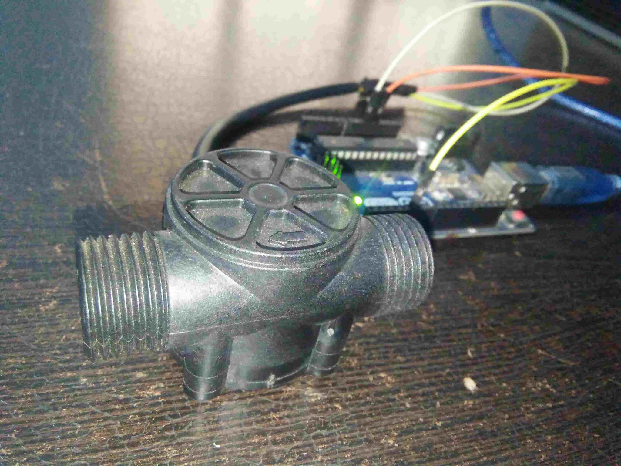
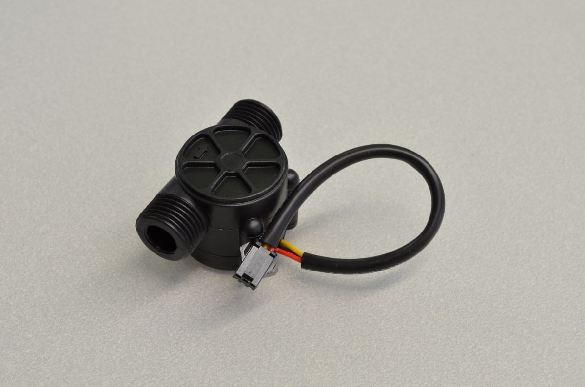
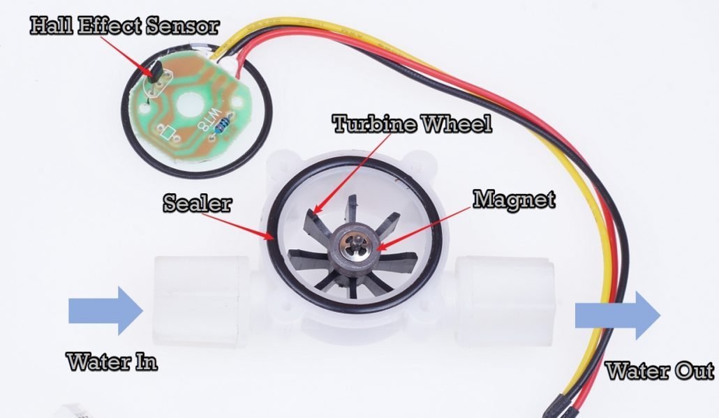
A Brief Note on Water Flow Sensor. Water Flow Sensor, as the name suggests, is a device to measure the flow of water. The Water Flow Sensor used in this project is shown in the image below. It has a plastic valve body with a rotor and a hall sensor circuit. It has three wires namely +5V (Red), GND (Black) and Output (Yellow).
Using A Flow Sensor With Arduino BC Robotics
Looking For Water Flow Sensor Arduino? We Have Almost Everything On eBay. But Did You Check eBay? Check Out Water Flow Sensor Arduino On eBay.
Flow Meter using Arduino
Step 1 - Power To The Breadboard. We are going to jump right in and set up the Arduino Uno and the breadboard right next to one another. The sensor works with anywhere between 5-18VDC but since we are working with 5VDC logic on the Arduino, we will just use the Arduino's own 5V power by way of the USB port at this time.
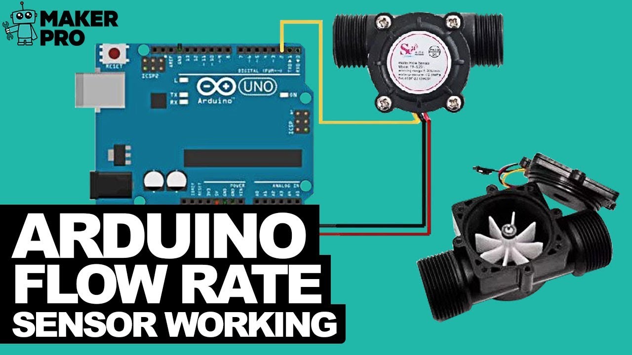
Arduino Flow Rate Sensor Working YouTube
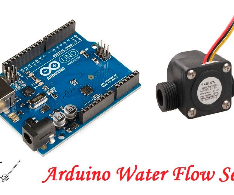
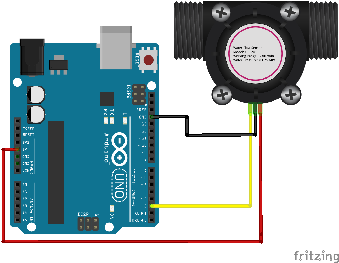
Features of Flow Sensor: Model: YF-S201. Sensor Type: Hall effect. Working Voltage: 5 to 18V DC (min tested working voltage 4.5V) Max current draw: 15mA @ 5V. Output Type: 5V TTL. Working Flow Rate: 1 to 30 Liters/Minute. Working Temperature range: -25 to +80℃. Working Humidity Range: 35%-80% RH.

Water Flow Sensor for Flow Rate & Volume Measurement using Arduino
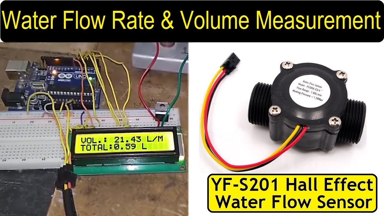
Then open your Arduino IDE and copy the code below. Download the code into Arduino. Note:. The code here is for the most classic YF - S201 Water Flow Sensor. However the picture above is YF - S402. Beacause we do not have YF - S201 in our hand. The code used for both is almost the same, with only one factor to be modified.
YFS201 WATER FLOW SENSOR INTERFACE WITH ARDUINO
Using the Flow Sensor with Arduino. The flow sensor in this tutorial contains three pins: VCC, GND, and OUT and are colored red, black and green respectively. This water flow sensor needs a 6 mm hose attached to its ends. Other models have larger inlet diameters. Note that water flow sensors work best with the help of gravity.
Using A Flow Sensor With Arduino BC Robotics
This type of sensor can be found on different diameters, water pressure (MPa) and flow rate (L/m) ranges. Make sure to select one that will cover your needs. The sensor that I have it has 20mm diameter, <1.75Mpa water pressure and ~30 L/m flow rate range. In this tutorial we will use the serial monitor for printing the water flow rate in liters.

Interfacing water flow meter with arduino uno
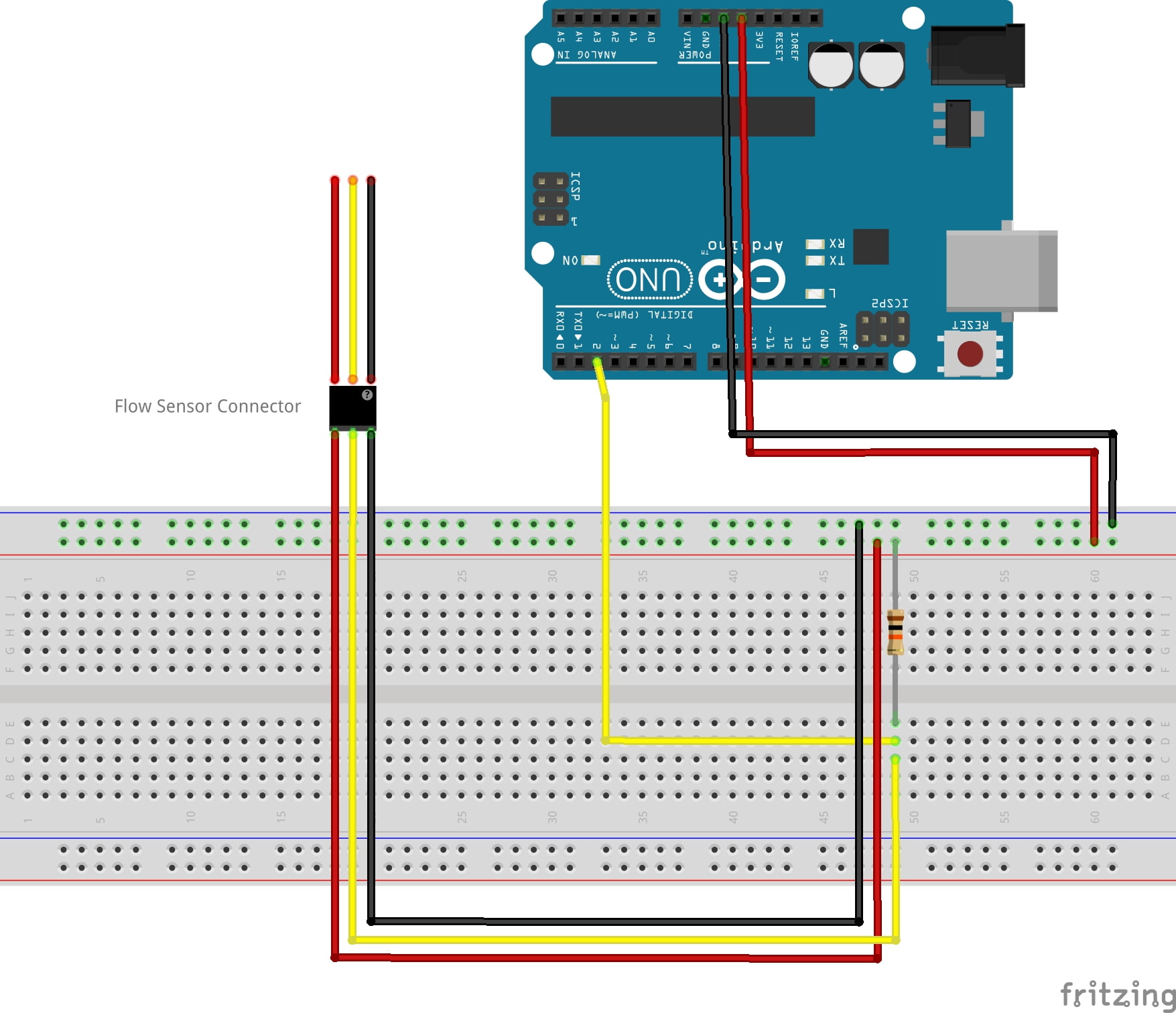
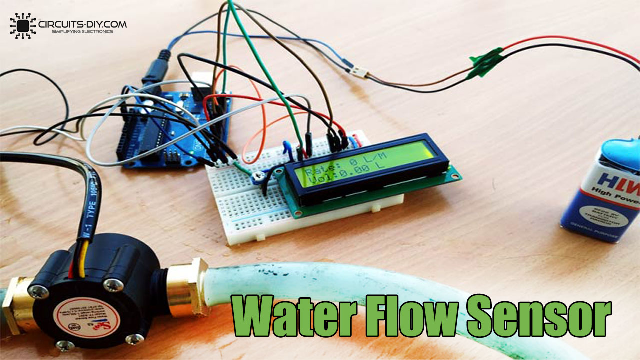
Hardware Hook Up. Connecting the water flow sensor to arduino requires minimal interconnection. Connect the VCC (Red) and GND (Black) wires of the water flow Sensor to the 5v and Gnd of Arduino, and link Pulse Output (Yellow) wire of the water flow sensor to Arduino's digital pin 2. Note that the water flow sensor is not a power-hungry type.
Arduino Water Flow Sensor Instructables
According to the datasheet of YF-S201 Water Flow Sensor, the output pulse frequency can be calculated with this equation: Pulse frequency = 7.5 x flow rate. The above equation can also be written as: flow rate = Pulse frequency / 7.5. Here pulse frequency is the number of pulse count in one minute. Hence:
Measuring Water Flow Rate and Volume using Arduino
The YF-S201 Water Flow Sensor is a hall-effect sensor designed to measure the rate of water flow passing through it. It utilizes the principle of the Hall effect, which involves the detection of changes in a magnetic field caused by the flow of fluid. This sensor generates electrical pulses proportional to the volume of water passing through it.

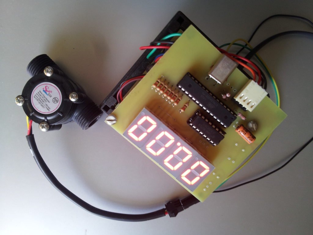
Water Flow Sensor Measure on 16x2 LCD Display Arduino Project Hub
For the water flow sensor the most important parameters are: Water Flow Rate Range. Max Water Pressure. Operating Voltage. You can find all the information in the table above, just make sure you choose the right water flow sensor with the right parameter. For Arduino Projects, if you are not sure which one to choose, just try YF-S201 and YF-S402.
Water Flow Rate & Volume Measurement using Water Flow Sensor & Arduino
The YFS201 Hall Effect Water Flow Sensor has three pins: VCC, GND, and OUT. To connect the sensor to an Arduino board. Connect VCC pin of the sensor to the 5V. Connect GND pin of the sensor to the GND. Connect OUT pin of the sensor to the digital pin D3. The connections are straight & simple, see the above circuit schematic image.
Water Flow Sensor Pinout & Interfacing with Arduino Measure Flow Rate
In this video, you will learn how to connect water flow sensor with arduinoComponents required to make this project are :1) Arduino UNO2) Arduino UNO Cable3).

Closed Loop Volume Controller Using Liquid Flow Sensors and Arduino
In this project, we will interface YFS201 Hall Effect Water Flow Sensor with Arduino for measuring flow rate and volume of water or any other liquid. This is.
Water Flow Sensor Pinout & Interfacing with Arduino Measure Flow Rate
The Water Flow Sensor used in this project is shown in the image below. It has a plastic valve body with a rotor and a hall sensor circuit. It has three wires namely +5V (Red), GND (Black) and Output (Yellow). Since it works on +5V, it can be interfaced with any microcontroller like Arduino, for example. If you notice the water level sensor.